 Failure problem: the connection between the GIGE interface card in the computer and the component camera is broken.
Unlock the Secrets of Effective Maintenance:Our Expert Tips for Troubleshooting Your ASM Mounter Accessories
Maintaining the peak performance of your ASM mounter requires a keen understanding of its intricate workings. When it comes to troubleshooting issues with the accessories, it’s crucial to have a clear and logical approach.
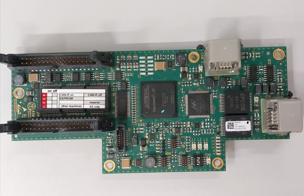
In this maintenance case, we identified a communication interruption as the root cause of the issue. To fix this, we needed to locate the IC responsible for communication. By using the data manual to assess the two canbus chips (82C251Y) next to the connector J6 port, we were able to determine whether they were functioning correctly.
Another key component to consider when troubleshooting is the communication logic IC (W262J) next to the J9 port, which controls the input of the LED control board of the component camera. Understanding how the image data transmission works through the J14/J16 port, the communication network filter (EPCOS), the DSP image processing chip, and the J11 port back to the PC, allowed us to quickly diagnose and fix the issue.
While the power supply and canbus communication signals through the J5 port are important, they were not the focus of our investigation. By having a targeted and comprehensive approach to maintenance, we were able to get your ASM mounter accessories back up and running in no time.
Don’t let issues with your ASM mounter accessories slow down your production line. Partner with us to get expert tips and troubleshooting solutions that will keep your equipment running at peak performance levels.
Let’s explain the pin definition of the image input and output port:
J11 (40pin): image data transfer port.
Pin4/10/16/22/28/34:DGND.
Pin1/7/13/19/25/31:DGND.
Pin2/3:GIG_LINE_00N/P.
Pin5/6: GIG_LINE_01N/P.
Pin8/9: GIG_LINE_02N/P.
Pin11/12: GIG_LINE_03N/P.
Pin14/15: GIG_LINE_04N/P.
Pin17/18: GIG_LINE_05N/P.
Pin20/21: GIG_LINE_06N/P.
Pin23/24: GIG_LINE_07N/P.
Pin26/27: GIG_LINE_08N/P.
Pin29/30: GIG_LINE_09N/P.
Pin32/33: GIG_LINE_10N/P.
J5 (16pin): power supply and Communication.
Pin1/2/3:42V.
Pin4/5/6:DGND.
Pin7/8:PORTAL_ID0/ID1.
Pin9/10:TRIGGER_HCU_P/N.
Pin11/14/16:DGND.
Pin12:24V.
Pin14/15:MCAN_L/MCAN_H.
J1/J9:PCB/ element camera LED control board control port.
J14/J16: component / PCB camera image data transfer port.